 Close the form.
Close the form.
 Commit form data to the database.
 Add an overhead construction to the corridor.
TO ADD AN OVERHEAD CONSTRUCTION TO THE CORRIDOR
Press the Add button. The Overhead Structure Library dialog box will appear to let you select a structure type for the new construction.
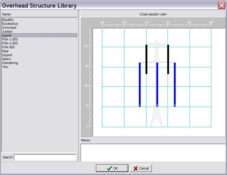
Select the structure type name in the list and press OK.
The Overhead Construction Properties dialog box will appear. Edit the overhead construction properties as needed.
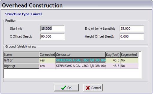
OVERHEAD CONSTRUCTION PROPERTIES
Start The construction’s starting-point coordinate, measured from beginning of the corridor.
End The construction’s end-point coordinate, measured from beginning of the corridor. If you enter a value in this edit box with the plus sign prefix, the program will interpret it as the length of the construction.
X Offset Horizontal-placement offset of the tower from the corridor centerline.
Height Offset This offset will be applied to the height of all phase and ground wires you specified in the overhead structure library.
For each ground wires of this overhead-structure type, enter the followings in the data grid:
Connected Whether the ground wire is being used in this construction.
Conductor Wire type from the wire library.
Sag
Catenary sag of the ground wire between towers. The sag must be zero or
positive.
NOTE: The program uses sag solely to compute
the conductor average height as H = Y – 2/3Sag for line constants
calculations.
Segmented Select “Yes” if the ground wire is segmented. See 2.5 GLOSSARY for the definition of a segmented ground wire.
 Edit the properties of the selected overhead construction. The Overhead
Construction dialog box will appear. See picture on last page.
Edit the properties of the selected overhead construction. The Overhead
Construction dialog box will appear. See picture on last page.
 Delete selected overhead construction.
 Replace selected structure
TO REPLACE AN OVERHEAD CONSTRUCTION
Press the Replace button. The Replace Structure Wizard will appear.
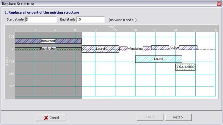
Enter values for “Start at mile” and “End at mile” distance from the beginning of the corridor where you want to replace the selected construction with a new one. Click on Next button to continue.
Note: “Start at mile” and “End at mile” value must be between the starting and ending point of the selected construction.
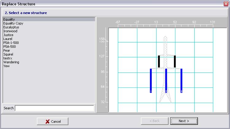
Select a new structure from the Structure browser and click Next to continue.
NOTE: new structure must have enough phase circuits for all currently connected line segments on the existing structure. Otherwise you will not be able to complete the next wizard step.
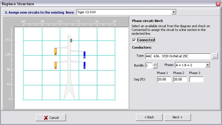
Select and connect circuit for all existing lines in the dropdown box. You may also select conductor parameters from this screen.
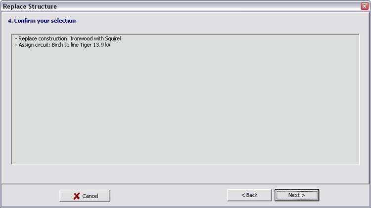
Review and click on “Next” to apply the changes to the database.
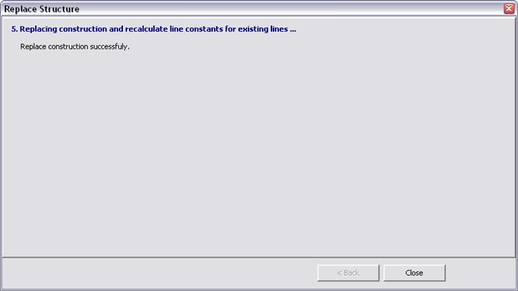
Wait for action to finish and click on “Close” to close the wizard.
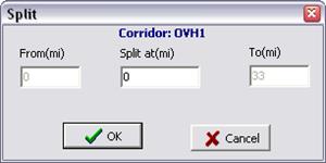
 Split corridor: Split one corridor in two separate new ones. A
dialog box will appear. Enter the “Split at” distance and press OK.
Split corridor: Split one corridor in two separate new ones. A
dialog box will appear. Enter the “Split at” distance and press OK.
 Join corridors: Join current corridor with another corridor. A wizard
dialog box will appear. Select a corridor you want to join from the corridor
browser to join with current corridor.
Join corridors: Join current corridor with another corridor. A wizard
dialog box will appear. Select a corridor you want to join from the corridor
browser to join with current corridor.
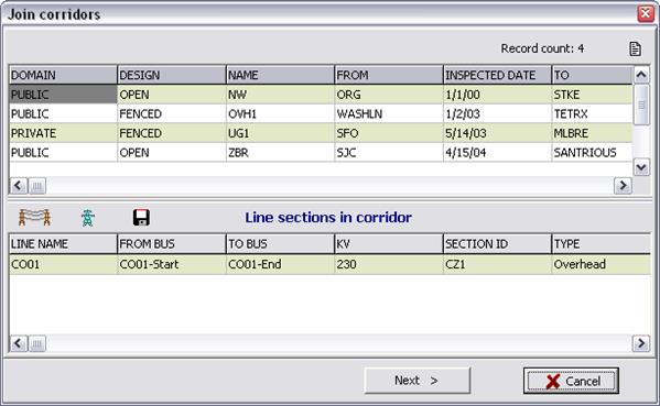
Select the connection point to join the selected corridor

 Bring selected object to the front. Designed for use when two or more
objects overlap, and the object of interest cannot be selected by clicking on
it.
Bring selected object to the front. Designed for use when two or more
objects overlap, and the object of interest cannot be selected by clicking on
it.
 Send selected object to the back. Designed for use when two or more objects
overlap, and the object of interest cannot be selected by clicking on it.
Send selected object to the back. Designed for use when two or more objects
overlap, and the object of interest cannot be selected by clicking on it.
 Manage file attachment in this corridor data record.
 Customize Info fields. The Administrator can use this command to enable/disable
form info fields, customize the field label, specify field display order on the
form and define dropdown pick list for text fields. See Section 3.16 CUSTOMIZABLE DATA
FIELDS for more information.
Customize Info fields. The Administrator can use this command to enable/disable
form info fields, customize the field label, specify field display order on the
form and define dropdown pick list for text fields. See Section 3.16 CUSTOMIZABLE DATA
FIELDS for more information.