The Add | Unstable-Power-Swing and Loss-of-Synchronism Region command in the DS Relays Window draws a dumbbell-shaped region – called the unstable power-swing region – on the R-X diagram according to the PRC-026-2 Standard Attachment B Criterion A. To comply with the PRC-026-2 standard, the relay characteristics must lie within this dumbbell-shaped region.
This command can be applied to a phase distance relay that protects a line, a transformer, or a generator.
Note: Zones with time delay longer than 15 cycles are exempt from PRC-026-2 requirements.
To calculate the unstable power swing region for relay that protects a line or transformer, the entire network is reduced to a 2-bus equivalent that comprises of the end buses of (1) the line or 2-winding transformer, or (2) the primary and secondary terminal of a 3-winding transformer. To calculate the current limit for relay that protects a generator, the entire network is reduced to a single bus equivalent at the generator bus that comprises of the generator and the equivalent system source. Two methods are available for calculating the equivalent network in this command:
(1) From apparent source impedance at the element’s terminals – this method uses fault simulations to calculate the sending-end and receiving end to form the equivalent network, following the process outlined in the Guidelines and Technical Basis for the PRC-026-2 Standard.
(2) From linear network reduction – this method uses linear network reduction techniques to calculate the sending-end, receiving end, and transfer impedances to form a reduced equivalent system.
The unstable power swing region is formed as the intersection of (1) a lower loss-of-synchronism circle based on ratio of the sending-end to receiving-end voltages of 0.7, (2) an upper loss-of synchronism circle based on ratio of the sending-end to receiving-end voltages of 1.43, and (3) a lens that connects the end points of the total system impedance by varying the sending-end and receiving-end voltages from 0.0 to 1.0 per unit while maintaining constant system separation angle across the total system impedance. (See picture below.)
TO DISPLAY THE UNSTABLE POWER SWING REGION:
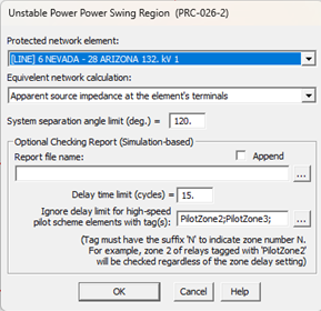
1. Select the Add | Unstable-Power-Swing and Loss-of-Synchronism Region command.
The Unstable power swing and loss-of-synchronism region dialog box will appear.
Note: This command is dimmed and cannot be execute if an unstable power swing region is already being displayed. To add a new unstable power swing region, you must first delete the existing one with the Delete | Unstable- Power-Swing and Loss-of-Synchronism Region command.
Note: This command is dimmed and cannot be executed if the first relay in the DS Relays Window is not a phase relay.
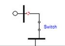
2. Select the protected network element. Relay terminal can be a line, a transformer or a generator. Relay protecting generator can be one end of a closed switch as shown below.
To specify desired end of line with tap buses, select the dropdown list item of “Select protected element”. The Add/Remove Line Segments dialog box will appear:
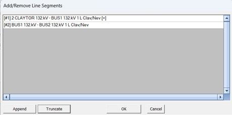
Use the controls in the dialog box to add new line segments to the list until all the end buses of protected line are included.
3. Specify the Source Impedance Calculation method: There are two options available: (1) From apparent source impedance at terminal bus(es), and (2) From linear network reduction.
3. Enter system separation angle limit. The default value is 120, which is the requirement in the PRC-026-2 standard.
4. Enter pathname of the checking report file (optional). When the report pathname is not blank, in addition to displaying the unstable power swing region the DS window, the program will also perform the automatic check of the relay performance along the boundary of the region and save the checking results in a report file. See help section for RELAY PERFORMANCE DURING STABLE POWER SWINGS COMMAND for additional details.
5. Enter the Delay time limit (cycles), if different than the default of 15 cycles.
6. Specify tags, if any, in the Ignore delay limit for high-speed pilot scheme elements with tag(s) section: This option currently has no effect when used with overcurrent relays. Select tags that will be used during while checking relay performance during stable power swings. These kinds of tags may be added to relays to specify zones for which the time delay should be ignored for the purposes of unstable power swing region evaluation.
7. Press OK.
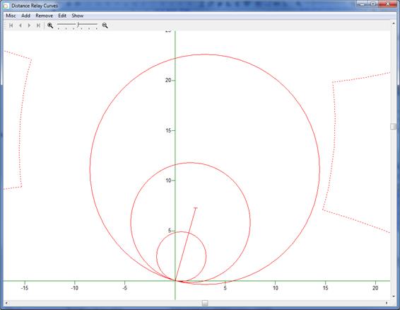
You will see a dotted dumbbell-shaped region on the R-X diagram immediately. This is a zoomed-out view.
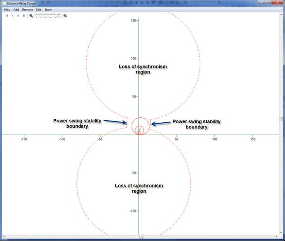
When viewed close-up, the relay characteristics and the unstable power swing region (draw with dotted lines) look like this. This distance phase relay conforms to the requirements of PRC-026 because its zone characteristics with trip time faster than 15 cycles are entirely within the dumbbell region.
The TTY Window documents the parameters of the network equivalent. It also lists the following:
1) 10 points for the right and left power-swing stability boundaries, assuming that the transfer impedance Ztr is neglected. A curve joining these points are plotted.
2) 10 points for the right and left power-swing stability boundaries, assuming that the transfer impedance Ztr is include. These points are not on the plot because they are less conservative.
3) The center and radius for the lower and upper loss-of-synchronism regions, assuming the transfer impedance Ztr is neglect. These circles are plotted.
4) The center and radius for the lower and upper loss-of-synchronism regions, assuming the transfer impedance Ztr is included. These circles are not plotted because they are less conservative.
DS Relays Window
ADD MENU