The Check Relay Performance during Stable Power Swings command in the Main Window allows you to quickly determine whether any of the phase distance relays and phase overcurrent relays that protect a line, transformer, or generator in the network could trip within a stable power swing region as defined in Standard PRC-026-2 attachment B.
This command can be used to check:
(1) Relays in a relay group, or
(2) Relays having a specified tag in (a) the general vicinity of a relay group, or (b) an area or areas (c) a zone or zones, (d) the entire network.
For options (1) and (2a), you must highlight a relay group prior to executing this command.
Two methods are available for calculating the equivalent network for this check:
(1) Apparent source impedance at the element's terminals – this method uses fault simulations to calculate the sending-end and receiving end sources to form a reduced equivalent system, following the process outlined in the Guidelines and Technical Basis for the PRC-026-2 Standard. The Fault Simulation preferences specified in the program options will be used to perform the simulations.
(2) Linear network reduction – this method uses linear network reduction techniques to calculate the sending-end, receiving end, and transfer impedances to form a reduced equivalent system. It is important to note that this method relies on linear network theorems, and therefore nonlinear models within the network, such as the CIR, Type-3, VCCS, and Current Limited Generator, are ignored when this method is used.
For each relay being checked, the program computes the unstable power swing region using the specified source impedance method and evaluates the possibility of relay operation per PRC-026-2 Attachment B Criteria A and B as described in sections UNSTABLE POWER SWING REGION COMMAND for distance relays and the UNSTABLE POWER SWING LIMIT COMMAND for overcurrent relays.
This command applies PRC-026’s application guidelines for generator protection relays when both of these conditions are met: 1) The relay-group bus has an in-service generator with a unit ID that does not begin with the Boundary Equivalent Equipment ID Prefix (as shown in the Network | Option command); and 2) The relay-group line/transformer or switch is the only device connected to the generator bus.
For all other relays on lines and transformers, PRC-026’s method for checking line and transformer relays will be used.
The program will verify whether the relay will show a trip time of less than 15 cycles on any point along the perimeter of the unstable power swing region. If no such point is found, the relay is declared to have met the PRC-026-2 requirements.
TO CHECK RELAY PERFORMANCE DURING STABLE POWER SWINGS:
1. Select the Check | Relay Performance during Stable Power Swings command.
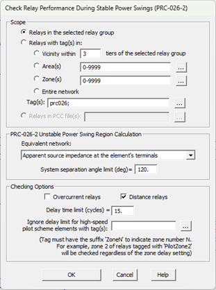
A dialog box will appear asking you to specify the checking parameters for lines, transformers and phase shifters.
2. Specify the relay types to be checked.
Mark the check box Overcurrent relays to check overcurrent phase relays. Mark the check box Distance relay to check distance phase relays.
3. Specify the checking extent.
There are six options available. The first two options are grayed and cannot be selected if you did not select a relay group prior to issuing this command.
The first two options are grayed and cannot be selected if you did not select a relay group prior to issuing this command.
Relays in the selected relay group: Click on this option to check the relays within the selected relay group only.
Relay with tag(s) in vicinity of selected relay group: Click on this option and enter a tier limit to check the relays that are in the vicinity of the selected relay group. Set tier to ‘1’ to check relays that are within one bus away from the selected relay group, and ‘2’ for relays within two buses away, and so on.
Relay with tag(s) in Area(s): Click on this option and enter the area numbers to check the relays within the selected areas. The area string can contain a mixture of ranges and numbers, e.g., “3-5,6,7,10-12”. Press the button “…” on the right if you need help in composing the area string.
Relay with tag(s) in Zones(s): Click on this option and enter the zone numbers to check the relays within the selected zones. The zone string can contain a mixture of ranges and numbers, e.g., “3-5,6,7,10-12”. Press the button “…” on the right if you need help in composing the zone string.
Relay with tag(s) in Entire network: Click on this option to check all tagged relays.
For the last four options above, Enter Tag(s). A relay record is considered tagged when: 1) it has the specified tags; or 2) is located in a relay group with the specified tags; or 3) is located on a piece of equipment that has the specified tags.
4. Specify the Equivalent Network Calculation method: There are two options available: (1) From apparent source impedance at element’s terminals, and (2) From linear network reduction.
5. Enter the System separation angle limit for unstable swing region calculation: PRC-026-2 Attachment B Criteria A and B specify that the unstable swing region must be computed with the system separation angle of at least 120 degrees, unless an angle less than 120 degree limit is documented in a transient stability analysis.
6. Enter the Delay time limit (cycles), if different than the default of 15 cycles.
7. Specify tags, if any, in the Ignore delay limit for high-speed pilot scheme elements with tag(s) section: Select tags that will be used during checking relay performance during stable power swings. These kinds of tags may be added to relays to specify zones for which the time delay should be ignored for the purposes of unstable power swing region evaluation. For example, a tag named “PilotZone2” may be added to a phase distance relay model to specify that the time delay setting of the Zone 2 element should be ignored while evaluating possible operation during a stable power swing.
8. Press OK to start checking.
The File Save dialog will appear asking you to specify the name and location of the checking report file.
Image files with graphic plots will be saved in the same disk folder as the report. If the XML file format is selected, OneLiner also creates a XSL style sheet file that will let you show a formatted display of the XML report data and graphic plot in a standard XML viewer software, such as Microsoft Internet Explorer or spreadsheet programs.
When the checking report generation is completed, the program will display a message box with the checking summary:
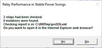
Click Yes to view the report in the Internet Explorer browser.
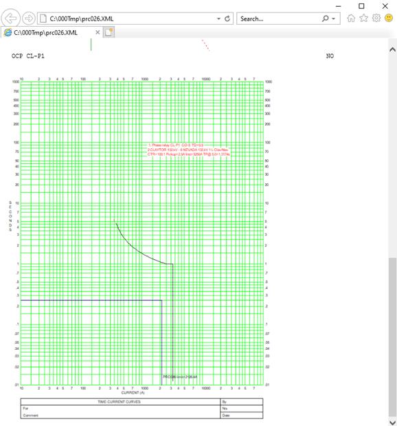
The two pictures below are from the browser display of the XML checking report of a phase distance and a phase overcurrent relay in the relay group on Claytor – Nevada 132 kV line.
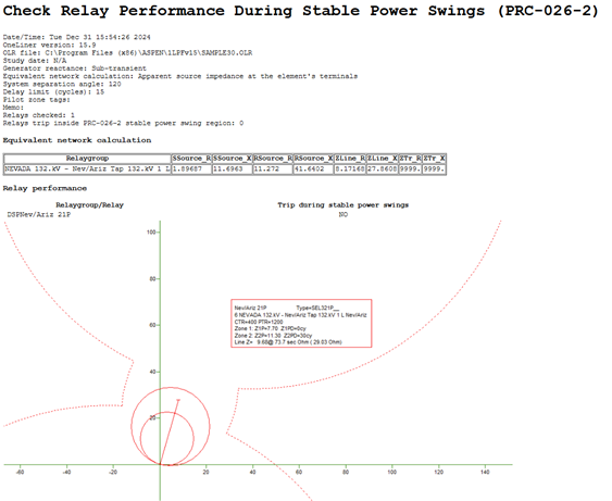
For a distance relay, the unstable power swing regions according to PRC-026-2 Attachment B Criterion A is shown as described in the help section for UNSTABLE-POWER-SWING AND LOSS-OF-SYNCHRONISM REGION COMMAND.
For an overcurrent relay, the unstable power swing limits according to PRC-026-2 Attachment B Criterion B are shown as described in the help section for UNSTABLE POWER SWING LIMIT COMMAND.
Each plot is labeled “Trip during stable power swings – Yes (or No)” at the upper right corner. “No” means it meet the requirements of the PRC-026-2 standard. “Yes” means it does not.
Calculation details are stored in the report under the following XML elements:
<PRC026REPORT> Results of the command execution. If you chose to append results to a report file, there will be multiple PRC026REPORT nodes in the file, one for each run. The node attributes are:
OLRVERSION: OneLiner program version string
DATETIME: Time and date of the report
OLRFILE: Full path name of the OLR file
SYSTEMSEPARATION: The system separation angle used in the calculation of the unstable power swing region.
ULOSSRVARATIO: The upper loss of synchronism region sending to receiving end voltage ratio
LLOSSRVARATIO: The lower loss of synchronism region sending to receiving end voltage ratio
GENZTYPE: generator reactance type used in in the calculation of the unstable power swing region.
CURRENTMULTIPLIER: the current multiplier used in checking relay performance.
DELAYLIMIT: the delay limit above which relay performance will not be evaluated.
SOURCEIMP: the method specified to calculate the source impedances.
IGNORESHUNT: the option specified for whether to ignore shunts in checking the relay performance.
IGNORELOAD: the option specified for whether to ignore load in checking the relay performance.
IGNORELINEGB: the option specified for whether to ignore line G+jB in checking the relay performance.
IGNORELINESHUNT: the option specified for whether to ignore line shunts in checking the relay performance.
PILOTZONETAGS: the pilot zone tags used to ignore element delay in checking the relay performance.
RELAYCHECKED: total relays checked
VIOLATIONS: total number of relays that found to trip on the perimeter of the unstable power swing region.
<RELAYGROUP> Checking results for one relay group. The node attributes are:
BRCODE: branch letter code: L- line; X-3 winding transformer; T- transformer; P- phase shifter; S- switch
CKTID: the branch circuit id
BUSNAME1, BUSKV1, BUSNAME2, BUSKV2: name and kV of branch buses
<EQUIVALENTNETWORK> Calculation results of the PRC-026-2 Attachment B equivalent network of the study element. The node attributes are:
R_BUSNAME, R_BUSKV, S_BUSNAME, S_BUSKV: Name and KV buses at of sending and receiving ends.
SSOURCE_R, SSOURCE_X: Sending source resistance and reactance in primary Ohm on the sending end bus kV level.
RSOURCE_R, RSOURCE_X: Receiving source resistance and reactance in primary Ohm on the sending end bus kV level.
ZLINE_R, ZLINE_X: Resistance and reactance of the study element (line or transformer) in primary Ohm on the sending end bus kV level.
ZTR_R, ZTR_X: Equivalent network transfer branch resistance and reactance in primary Ohm on the sending end bus kV level.
<CRITERION_A> Calculation results of the PRC-026-2 Attachment B Criterion An unstable power swing region.
<LOSSOFSYNC> Calculation results of the PRC-026-2 Attachment B Criterion An unstable power swing region loss of synchronism regions. The node attributes are:
UCENTERX_R, UCENTER_R, URADIUS: Coordinates of the center and the radius of the upper loss of synchronism region circle
LCENTERX_R, LCENTER_R, LRADIUS: Coordinates of the center and the radius of the lower loss of synchronism region circle
ZTRREMOVED: flag to show whether or not the transfer impedance branch is included in the calculation
<LEFTSIDELENS> Calculation results of the PRC-026-2 Attachment B Criterion An unstable power swing region left side lens. The node attributes are:
ZTRREMOVED: flag to show whether or not the transfer impedance branch is included in the calculation
<RXPOINT> Calculation results of the PRC-026-2 Attachment B Criterion A unstable power swing region left side lens boundary. The node attributes are:
VRATIO: Sending end to receiving and source voltage ratio
R, X: Coordinate of the point on the lens boundary
IREAL, IIMAG: the relay performance check current in amps
VREAL, VIMAG: the relay performance check kV, Line to neutral.
<CRITERION_B> Calculation results of the PRC-026-2 Attachment B Criterion B unstable power swing region. The node attributes are:
PRIAMPS: the relay performance current magnitude in amps.
<DSRELAY> Calculation results of the distance relay performance on the perimeter of the unstable power swing region. The node attributes are:
NAME: the relay name
CTR: the CT ratio
ZONEREACH1, ZONEREACH2, ZONEREACH3: the relay zone reach settings
VIOLATION: whether or not the relay tripping time of faster than 15 cycle was found at any point on the perimeter of the unstable power swing region.
IMG: Name of the image file with the graphic plot of the relay characteristic and the unstable power swing region. The image file name is composed from the branch bus names and relay name strings.
<UNSTABLESWING_LIMIT> Relay performance calculation at a point on the perimeter of the unstable power swing region. The node attributes are:
IREAL, IIMAG: the relay performance check current in amps
VREAL, VIMAG: the relay performance check kV, Line to neutral.
TRIPTIME: the relay trip time
<OCRELAY> Calculation results of the overcurrent relay performance on the perimeter of the unstable power swing region. The node attributes are:
NAME: the relay name
CTR: the CT ratio
PICKUP: the relay pickup setting
INST: the relay Instantaneous pickup setting
TESTAMPS: the relay performance check current in amps
TRIPTIME: the relay trip time
VIOLATION: whether or not the relay tripping time of faster than 15 cycle was found at any point on the perimeter of the unstable power swing region.
IMG: Name of the image file with the graphic plot of the relay characteristic and the unstable power swing region. The image file name is composed from the branch bus names and relay name strings.
Main Window
CHECK MENU