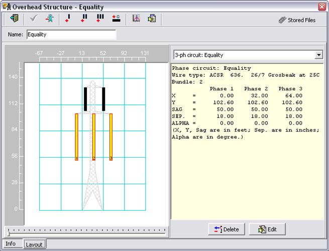
The Layout tab has a diagram panel on the left and a properties panel on the right.
The diagram panel displays a cross-section view, drawn in the perspective of an observer looking in the direction of the wires. The ghosted image of the tower is for illustrative purposes only, and does not correspond to tower’s physical design. Conductors in phase circuits and ground wires are depicted on the diagram as vertical bars. The top of each bar shows the height of the wire on the tower. The height of the bar represents the catenary sag between adjacent towers. When the user clicks on a conductor in the diagram with the mouse, the corresponding circuit or ground wire properties are displayed in the panel on the right. The user can alternatively select phase circuits and ground wires from the drop-down combo box above the properties panel.
The data fields on this form − other than the Name − are read-only. Please see text under headings “Circuit Properties” and “Ground Wire Properties” below on how to modify the data.