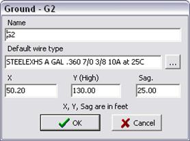
To edit the properties of a ground wire, click on a ground wire in the diagram panel. Alternatively, select a ground wire in the dropdown list. Press Edit to bring up the ground-wire dialog box..
Name A name that identifies this ground wire. The name is limited to 40 characters.
Default wire type The most commonly used wire type for this ground wire. You can leave this item blank if you do not wish to provide a default type. In any case, the user can override the default wire type when an instance of this tower type is used in a construction.
Coordinates ‘X’ is the horizontal distance from the center of the overhead structure. ‘Y (High)’ is the height of the wire at the tower. The unit for X and Y (either feet or meters) is shown near the bottom of this form. The height Y must be positive. With the exception of the position-offset parameters, the user will not be able to change the wire coordinates when this tower type is used for a construction.
Sag
Default value for the catenary sag at the midpoint between towers. The unit for
the coordinates and the sag (feet or meters) is at the bottom of this dialog
box. The sag must be zero or positive.
NOTE: The program
uses sag solely to compute the conductor average height as H = Y – 2/3Sag for
line constants calculations.
Note: Modifying the circuit and ground wire coordinates in the library will affect line constants results in all lines that utilize the structure type.