Each overhead line is modeled as a series of line sections in one or more corridors. You must associate each line section with a circuit on a construction. (Note: A construction, such as one with a double-circuit tower, can have multiple circuits.)
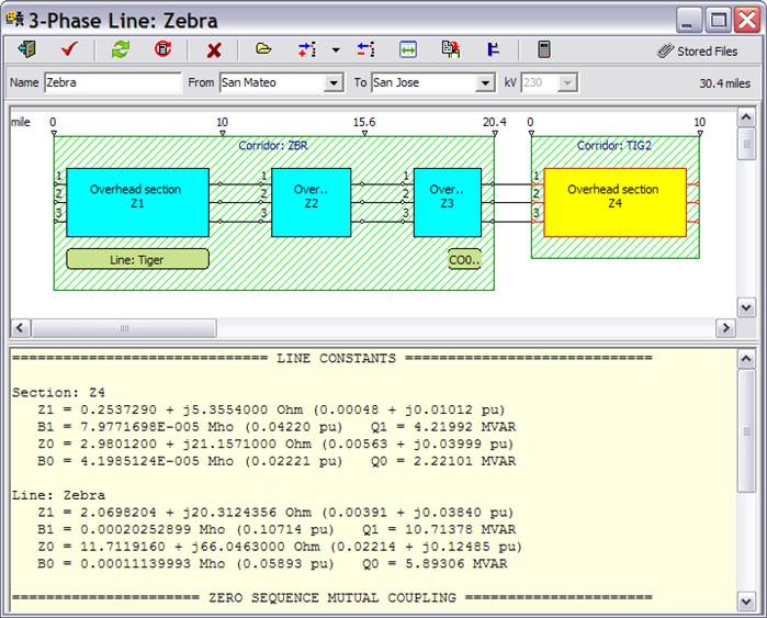
The following window shows a 3-phase line called Zebra with four sections named Z1, Z2, Z3 and Z4. The first three sections are on three consecutive constructions in corridor ZBR. Cross-referencing these sections with the previous picture of corridor ZBR shows that the sections are those with tower types Eucalyptus, Laurel, and Wandering. The last section Z4 is on a different corridor named TIG2.
Markers along the top of the corridor box show the coordinates of the section end points. The phase connection between consecutive sections is shown graphically. In this example, the phase wires are not transposed.
Additional rectangles in the space below the first row of line sections tells us that there are sections of two other lines (called Tiger and CO01) in the same corridor. A section for the line Tiger goes from mile 0 to mile 10. A section of line CO01 goes from mile 15.6 to mile 20.4. These two lines may have sections in other corridors.
The text in the bottom half of this form shows the overall electrical parameters Z1, B1, Q1, Z0, B0 and Q0, of the entire line, as well as the parameters Z1, B1, Q1, Z0, B0 and Q0 for the selected section Z1. (Only the parameters of the entire line are visible in this snapshot).
The bottom portion of the info panel shows the zero-sequence mutual coupling impedance, in pairs, between this line and all other lines that run parallel with it. In this case, there are two possible pairs of lines: between line Zebra and Tiger, and between Zebra and CO01. The mutual coupling parameters of the Zebra-Tiger pair are visible in the picture.