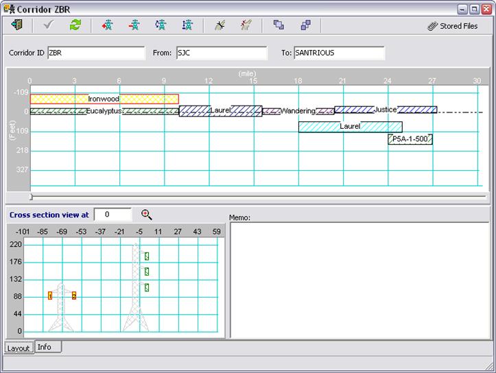
The top view panel in the Layout tab shows a top view of the corridor layout. The following convention is used to distinguish between different objects:
•Shaded rectangular block with square corners: A “construction”, a single, continuous run of one kind of tower. The text within each construction rectangle is the name of the tower type.
•Shaded rectangular block with rounded corners: An underground cable section. The text within each underground-cable section is the name of the cable type.
•Shaded rectangular block with rounded corners and no text: An impedance line section.
You can view the construction/cable-section/impedance-section
properties by double-clicking on any of the rectangular blocks. If two blocks
overlap, a mouse click will select the object on top. To select a block that is
not on top, you can (1) select the object that is on top and press the “Send to
back” button  one or more times until
the desired block comes to the top, and (2) click on the block to select it.
one or more times until
the desired block comes to the top, and (2) click on the block to select it.
The cross-section view in the bottom panel of the Corridor Form
shows the circuits at a certain distance shown in the “Cross section view at”
edit box. This picture is drawn from the perspective of an observer standing on
the right-of-way looking in the direction of the conductors. In this example,
the cross-section at 18 mile shows the two constructions with tower types
“Wandering” and “Laurel”. You can change the cross-section view point by
entering the coordinate in the “Cross section view at” edit box and click on the
View button  . You can alternatively change
the cross-section view point by dragging the slider control beneath the top
panel.
. You can alternatively change
the cross-section view point by dragging the slider control beneath the top
panel.
Note: Cable sections and impedance sections are not shown in the cross-section view.