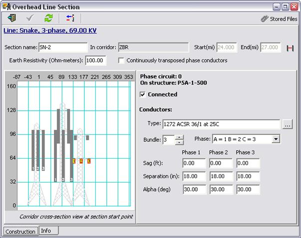
Once you selected the corridor and the starting and ending distance, the constructions are shown graphically in the Construction panel of the Overhead Line Section Form. A sample Overhead Line Section Form is repeated below for ease of reference.
Now you must associate the line section with a circuit in this picture. Some of the circuits are drawn in a dark gray color. These are circuit that have different number of phases and circuits that are already connected to other lines. You must choose one of the remaining circuits that are not gray. In this example, the only available circuit is a 3-phase circuit on the rightmost tower.
TO SELECT OR EDIT A PHASE CIRCUIT
1. Click on an available circuit in the cross-section view. The selected circuit will be shown in orange. The parameters of the selected circuit are shown to the right of the picture. In the example, a 3-phase circuit was selected.
2. Mark the check box Connected. The “connected” flag tells the program that the phase circuit has been associated with a line section.
3. For a new line section, the parameters are set initially to the default values from the overhead structure library. Modify the phase-circuit parameters if necessary: Conductor type, bundle settings, phase assignment, sag, separation and alpha.
Note: It is possible to associate a line section with multiple phase circuits. The most common application is a 3-phase line that utilizes the wires that were originally built for two separate circuits on a double-circuit tower. In this case, you need to repeat the last three steps for each of the two phase circuits on the tower.
TO REMOVE PHASE CIRCUIT FROM THE LINE SECTION
1. Click on the circuit in the cross-section view.
2. Uncheck the check box labeled Connected